ABSTRACT: Drilled shafts socketed in crystalline rock salt are a common type of foundations used in the Dead Sea region to support high vertical and lateral loads. The existing subsurface condition consists of soft clay followed by crystalline salt. Due to the difference in nature and geological features, the performance of such foundation types under vertical loading in the crystalline rock salt is different from their known behavior in common rock types. This paper is an attempt to understand the real behavior of socketed drilled shafts in crystalline salt through a finite element modeling of a field pile load test carried out in this formation. The studied case is of a steel tubular pile provided with a reinforced concrete socket in the crystalline salt formation. The prevailing salt layers in the pile test area are highly fractured crystalline rock salts of variable strength ranging from weak to moderately weak. Full details of the pile load test, a description of the subsurface conditions and salt strength tests are presented in this paper along with the finite element analysis details and results. The developed shear resistance along the socket length of the pile is verified and compared to the commonly used correlations for rock formations. The performed analyses and comparison with the field pile load test results provided a better understanding and good information about the drilled shafts’ performance under vertical loading conditions in such
formation. The analyses carried out in this paper deal with the short-term behavior of the Dead Sea rock salt as the creep effect directly impacts the long-term performance.
1. INTRODUCTION
Behavior of concrete piles socketed in rock depends on many factors such as the rock strength, rock quality, concrete strength, drilling fluids effect and roughness of the interface surface. Rock characteristics are highly affected by weathering and environmental conditions. Finite element analysis (F.E.) has proven a good ability to simulate the soil and rock behaviors in wide range of civil engineering applications. For the study of the performance of piles socketed in the Dead Sea crystalline rock salt using the F.E. approach, choosing the reasonable constitutive model is an essential factor. Accordingly, in this paper three different constitutive models that are the Linear Elastic (LE), Mohr-Coulomb (MC) and the
Hardening Soil (HS) have been investigated. The geotechnical parameters of the rock salt needed for the
different models were estimated based on several sources that are the laboratory tests, in-situ tests and the back analysis of the field pile load test results. More emphasis in choosing the geotechnical parameters was given to the in-situ tests results and the back analysis outcome to eliminate the scale effect playing an important role in the laboratory tests results.
2. GEOLOGY OF THE DEAD SEA AREA
The Dead Sea occupies the lowest basin on the continental part of the earth. It strikes in an almost N-S direction. The width of this basin varies in the range of 10-18 km, and its length is about 80 km, though only its northern 55 km is still covered with water in the present. Its maximum depth is about 750 m below mean sea level. The Dead Sea is a complex structural feature bordered by two faults, the first is the Wadi-Araba fault that runs from the Gulf of Aqaba to the north over some 190 km and the second is Jericho fault that seems to start some 20 km west of the northern end of the Wadi-Araba fault in the western part of the Dead Sea and runs in a NNE direction to the Tiberias lake over a length of about 150 km [1]. The Dead Sea is accordingly considered as a rift (tensional graben). It would be inferred that the Dead Sea is the result of the left lateral motion between the Arabian and Sinai plates which is known as pull-apart [2]. Tectonics of the Middle East are controlled by the Dead Sea Transform (DST) fault system, a major tectonic accident responsible for most recent structures of the region. The DST forms the accurate plate boundary between the Arabian plate and the Sinai plate, so at a global scale, the DST is a part of the boundary between the African and Arabian plates as shown in Figure (1), that probably started forming around 20 M.Y. ago. The DST strikes from N15°E to N20°E and extends over some 1100 km from the Red Sea northwards, where crustal spreading occurs, along Wadi-Araba, Dead Sea, Jordan valley, lake Tiberias and central Lebanon to the continental collision zone in the Taurus-Zagross mountain belt. Regional uplift and basaltic volcanism are characteristics of the DST and the Red Sea region. More than 3 km uplift is believed to have taken place in the Red Sea since the Oligocene. In the Dead Sea region, uplift is of the order of 1-2 km. The Arabian plate and Sinai plate are both moving northward within the more general context of the active African-Eurasian convergence, but the Arabian plate is moving faster than the Sinai plate, because Arabia is integrating a supplementary component of motion resulting from the oblique opening of the Red Sea [3].
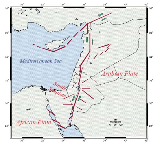
Fig. 1. General trends of the DST (after Mohsen [1])
The Dead Sea is one of the saltiest bodies of water on Earth with a salinity of about 300 parts-per thousand (nine times greater than ocean salinity) and is fed by the Jordan River. The mineral content of the Dead Sea is significantly different from that of ocean water, consisting of approximately 53% magnesium chloride, 37% potassium chloride and 8% sodium chloride. In the early part of the 20th century, the Dead Sea began to attract interest from chemists who deduced that the Sea was a natural deposit of potash and bromine. From the Dead Sea brine, Israel and Jordan produce 3.8 million tons of potash, 200,000 tons of elemental bromine, 45,000 tons of caustic soda, 25,000 tons of magnesium metal, and sodium chloride. Both countries use extensive salt evaporation pans that have essentially diked the entire southern end of the Dead Sea [4]. Figure (2) shows the Dead Sea, and the dikes constructed by Jordan and Israel for the Potash and other chemicals production. The northern 50 km-long part of the Dead Sea basin is a hypersaline lake with a minimum elevation of 720 m below sea level, whereas the southern part of the basin is subaerial with a minimum elevation of 410 m below sea level. Basin fill consists of lacustrine and fluvial sediments that were deposited in the basin since the middle to late Miocene as explained in Figure (3). These continental sediments lack suitable fauna for dating. A mostly evaporitic sequence, the Sedom formation is also present within the basin fill. The formation, as defined in the Sedom diapir, consists of about 80 % halite, with the remainder gypsum, marly chalk, dolomite and shale. Studies indicate that the chemical composition of the evaporites is the result of mixing between seawater, fresh water, and the limestone rock wall of the basin [5].

Fig. 3. Stratigraphy of the Dead Sea basin (after Al-Zoubi [5])
The Lisan Peninsula, previously a peninsula within the lake, but now at the southern edge of the shrinking lake, is a structurally complex region elevated by large Lisan salt diapir. Surface elevation of the peninsula is now higher than 50 m above the adjacent basin to the south. The salt diapir is covered by 125 m or more of upper Pliestocene (Lisan Formation) and Holocene sediments. Another salt diapir, the Sedom diapir shown in Figure (4), is located to the southwest. The diapir has pierced the surface creating an approximately 200 m high ridge where an approximately 2 km thick section is exposed. The evaporites in the Dead Sea basin were deposited via an ingression of the Mediterranean Sea to the Dad Sea rift about 80 km north of the Dead Sea. Connection to the Mediterranean Sea was permanently served during the Pleistocene when the land west of the rift valley began to rise.

Fig. 4. Lisan and Sedom diapirs (after Al-Zoubi [5])
3. GEOLOGICAL CONDITIONS AT THE AREA UNDER STUDY
Generally, at the area where the pile load test site is located as shown in Figure (2), the stratigraphy consists of the following units, from the oldest to the youngest [6]:
a) edom formation Pliocene: Predominantlycrystalline salts.
b) Lisan Formation: alternating layers of soft to firm Predominantly crystalline grey silty carbonate clay, thinly laminated with silt sized aragonite. The laminations vary in thickness from 0.1 mm to a few millimeters. The aragonite laminations are locally cemented to form hard undulated carbonate sheets. Thin layers of gypsum are also relatively common in the formation.
c) Surficial Deposits – Holocene: this formation is made of evaporites, crystalline halite, laminated
marl, inter-fingered with clay, silt, sand and gravel that had been deposited in deep shallow water.
4. SUBSURFACE CONDITIONS
From the carried out offshore site investigations at the pile load test location comprising drilling of boreholes and carrying out pressuremeter and vane shear tests, the subsurface conditions were found to be consisting of a thick layer of soft clay with a thickness of about 16.50 m followed by an extended layer of competent crystalline rock salt.
4.1 Soft Clay Parameters
According to the site investigation results, vane shear tests and the study made by El-Mossallamy [6], the shear strength values of the soft clay layer, in general, increase with depth according to the following equation: A conservative value of Cu = 5.0 kN/m2 is considered in the analyses in this paper.
4.2. Crystalline Rock Salt (Halite) Parameters
The adopted parameters for the crystalline rock salt are derived from the uniaxial compression tests and
pressuremeter tests carried out in the vicinity of the pile load test location. The uniaxial compressive strength results vary between approximately 3.0 MPa to approximately 9.20 MPa with an average value of about 5.10 MPa. The deformation modulus of the rock salt varies between approximately 144 MPa to approximately 194 MPa from the uniaxial compression tests while varying between approximately 18 MPa to approximately 196 MPa from the pressuremeter tests. The performed pressuremeter tests included cyclic loadings showing that, in general, the rock salt gets stiffer in the unloading-reloading condition and gets even stiffer after repeating the unloading-reloading for more than one cycle. For the first cycle of unloading-reloading, an average (Eur/E) value of approximately 4.30 was recorded, while an average (Eur/E) value was recorded as approximately 8.50 in the second unloading-reloading cycle. A conservative value of the (Eur/E) of about 3.0 was implemented in the current analyses. The RQD values of the massive competent rock salt vary between about 37% to about 94% with the values in general increasing with depth. An average value of the RQD for the competent massive rock can be chosen in the range from 60 % to 80 %. Based on the deformation modulus (E) values obtained from the uniaxial compression tests, pressuremeter tests and considering the RQD values of the competent massive rock salt and from the preliminary F.E. analysis, an elastic modulus deformation value of approximately190,000 kPa was adopted in the analyses in this paper.
5. FIELD PILE LOAD TEST
5.1. Test Pile
Figure (5) shows the general configuration of the test pile as explained by Gibb [7]. The test pile is made from longitudinally welded tubular steel sections of 914mm outer diameter and a wall thickness of 17.5mm. The pile length is 26.88m. The outer sleeve is made from 1220mm outer diameter tubular steel sections and of a wall thickness of 16.0mm.

5.2. Test Pile Rig
Four temporary piles were driven around the test pile. These piles were closed-ended for ease of extraction after test completion. A structural steel frame was then erected on top of these piles to transfer the kentledge load to the four temporary piles and to provide reaction from the loading jack placed on top of the test pile.
5.3. Pile Load Test
The 1220 mm diameter sleeve was driven to the competent rock stratum using a Vibro hammer. The
sleeve was then emptied from the inside clay and rock using hand and airlifting. The steel test pile was then placed inside the sleeve. Drilling of the rock socket was carried out subsequently. The steel pile was then re-driven a further 0.50 m into the rock salt. In order to ensure that the pile load will be taken fully through skin friction, avoid was created beneath the socket tip using avoid former. The reinforcement cage was extended upwards to suspend it from the top of the test pile and hence off the base of the rock socket. The reinforcement cage was modified at the base to enable a void former to be attached
to it. The concrete was placed into the pile using a 30m long x 250mm diameter tremie tube [7].
5.4. Loading Cycles
The test pile was loaded on cycles as follows:
Load Cycle 1: 0, 150, 300, 450, 689, 450, 300, 150, 0 kN.
Load Cycle 2: 0, 600, 750, 900, 1050, 1200, 1373, 1050, 900, 750, 600, 450, 300, 150, 0 kN.
Load cycle 3: 0, 600, 900, 1200, 1350, 1500, 1680, 1500, 1350, 1200, 1050, 900, 750, 600, 450, 300, 150, 0 kN.
5.5. Settlement Monitoring
Pile settlement was monitored using three dial gauges positioned equidistant around the pile. Two of the dial gauges were supported from a reference beam spanning below the test rig and fixed to two independent piles while the third one was supported from the 1220 mm sleeve. The temporary and independent piles were monitored for settlement throughout the three loading cycles by automatic level readings. Figure (6) shows the pile load test results of the three performed cycles.
5.6. Comments and Observations on the Load Settlement Curve
From Figure (6) showing the load-settlement curves of the carried out pile load test, the following observations can be noticed:
a) The main characteristic that can be noticed is that, repeating the loading values by cycling, results in
softening in the rock formation in the shape of an increase in the settlement under the same repeated load. This phenomenon is observed just under relatively high loadings (i.e. lodging cycles 2 and 3).
b) The rock salt behavior can be considered as elastic where no residual plastic deformations were recorded after unloading.
c) Some disturbance in the deformation results can be noticed at the very initial part of the load-settlement curves for all cycles that can be referred to the low accuracy of the dialing gauges at the very low deformation values.
6. CONSTITUTIVE MODELS
Throughout the current research, three soil constitutive models were investigated for their capability to
reasonably model the rock salt behavior in the short-term condition. These models are the linear elastic model (LE), the linear elastic perfectly-plastic Mohr-Coulomb model (MC) and the Hardening Soil model (HS). A brief description of the different models along with their limitations is given below as explained in the PLAXIS 2D, version 8.20 materials manual.
6.1. Linear Elastic Model(LE)
The Linear Elastic model is based on Hooke’s law of isotropic elasticity. It involves two basic elastic
parameters, i.e. Young’s modulus, E, and Poisson’s ratio, . Soil behavior is highly non-linear and irreversible. The linear elastic model is insufficient to capture the essential features of soil. The use of the linear elastic model may, however, be considered to model strong massive structures in the soil or bedrock layers. The linear elastic model was investigated to model the competent rock salt layer.
6.2. Mohr-Coulomb Model(MC)
The linear elastic perfectly-plastic Mohr-Coulomb model involves five input parameters, i.e. E and for soil elasticity; and c for soil plasticity and as an angle of dilatancy. The Mohr-Coulomb model represents a ‘first order’ approximation of soil or rock behavior. For each layer a constant average stiffness or a stiffness that increases linearly with depth is to be estimated. Due to the constant stiffness, computations are relatively fast and first estimate of deformations can be obtained. The linear
elastic perfectly-plastic Mohr-Coulomb model is a first order model that includes only a limited number of features that soil behavior shows in reality. Although the increase of stiffness with depth can be taken into account, the Mohr-Coulomb model does neither include stress dependency nor stress-path dependency nor strain dependency of stiffness or an isotropic stiffness. In general, effective stress states at failure are quite well described using the Mohr-Coulomb failure criterion with effective strength parameters ’ and c’. Figure (7) shows the basic principle of the elastic-perfectly plastic model while Figure (8) shows the Mohr-Coulomb yield surface in the principle stresses space.

Fig. 7. Principles of the elastic perfectly-plastic model

Fig. 8. Mohr-Coulmob model yield surface
6.3. Hardening Soil Model (HS)
The Hardening Soil model is an advanced model for the simulation of soil behavior. As for the Mohr
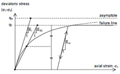
Coulomb model, limiting states of stress are described by means of the friction angle,, the cohesion, c, and the dilatancy angle, . However, soil stiffness is described much more accurately by using three different input stiffnesses: the triaxial loading stiffness, E50, the triaxial unloading stiffness, Eur, and the Oedometer loading stiffness, Eoed· In contrast to the Mohr-Coulomb model, the Hardening Soil model also accounts for the stress-dependency of stiffness moduli. This means that all stiffnesses increase
with pressure. In contrast to an elastic perfectly-plastic model, the yield surface of a hardening plasticity model is not fixed in the principal stress space, but it can expand due to plastic straining. A distinction can be made between two main types of hardening, namely shear hardening and compression hardening. Shear hardening is used to model irreversible strains due to primary deviatoric loading. Compression hardening is used to model irreversible plastic strains due to primary compression in Oedometer loading and isotropic loading. Both types of hardening are contained in the HS model. Then Hardening Soil model is an advanced model for simulating the behavior of different types of soil, both soft soils and stiff soils. When subjected to primary deviatoric loading, soil shows a decreasing stiffness and simultaneously irreversible plastic strains develop. In the special case of a drained triaxial test, the observed a relationship between the axial strain and the deviatoric stress can be well approximated by a hyperbola. The Hardening-Soil model, however, supersedes the hyperbolic model by far, firstly by using
the theory of plasticity rather than the theory of elasticity, secondly by including the soil dilatancy and
thirdly by introducing a yield cap. Figure (9) shows the Hyperbolic stress-strain relation in the primary loading condition for the standard drained triaxial test for clarification of the main elastic moduli
used in the HS model that are; the initial tangent stiffness modulus Ei, the unloading-reloading modulus Eur and secant stiffness at 50% of strength E50. Yield contour of the model in three-dimensional space is shown in Figure (10).

7. FINITE ELEMENTS MODEL
Finite elements analysis was used to simulate the behavior of a test pile socketed in the crystalline
massive rock salt of the Dead Sea. Due to the axisymmetric nature of the loaded element and the
applied load, the axisymmetric model was used. The finite element package PLAXIS 2D, version 8.20 was
used for this purpose. The loaded pile consists of two segments; a 26.88 m steel part made from welded
tubular sections of 914mm outer diameter and a wall thickness of 17.5mm, and a reinforced concrete part
that is socketed in the crystalline rock salt formation of a diameter of 810 mm. The socket part into the
crystalline rock salt is of a length of 2.35 m. During the pile load test and in order to study the shear interface between the rock socket and the competent rock salt, avoid was left below the base of the concrete rock socket. This enabled the shear interface component of the pile to be separated from end bearing component. The test pile was sleeved in order to remove the effect of skin friction on the pile from the soft clay stratum overlying the competent rock stratum. The used sleeve was made of steel with an outer diameter of 1220 mm, a thickness of 16 mm and with a total length of 25.40 m.
7.1. Load Cycling Simulation
The developed finite elements model strictly followed the pile load test under study. The total multipliers were used to simulate the load cycles and stages of loading and unloading as carried out in the field. The load at the different stage was simulated by uniform stress acting on the pile head.
7.2. Materials, Interface and Constitutive Models
Throughout the performed F.E. analyses using PLAXIS, the shear along the interface between different materials is modeled using elastic-plastic interface elements. The interface elements properties are linked to the strength properties of the soil/rock layers. The main interface parameter in the analysis is the strength reduction factor Rinter. While the case under study comprises only four different materials that are; the steel pile of tubular section, the concrete socket, the soft clay and the crystalline rock salt layer, six materials types were used in the F.E. analyses. The additional two materials are related to the void beneath the pile tip in which an elastic material with very weak properties was adopted in the analyses, and another salt layer was defined with the same parameters of the crystalline rock salt layer surrounding the socketed part of the pile but with almost a zero strength reduction factor Rinter, to simulate a non-shear interaction effect between the steel pile and the salt (along the 0.50 m of the steel pile
driven into the salt). A zero Rinter value was used as well along the steel pile in the soft clay layer simulating the sleeve effect isolating the steel pile from the surrounding soft clay. Full shear interaction between the concrete socket and the surrounding rock salt was modeled using a strength reduction factor Rinter equal to 1.0. In the F.E. model, the concrete socket and the steel tubular section pile were modeled utilizing the linear elastic (LE) model. The soft clay layer that is almost has no effect in the analysis except for its overburden pressure on the rock salt layer was modeled using the Mohr-Coulomb (MC) constitutive model. For the rock salt layer, three different constitutive models were investigated in which the analysis results are presented later in this paper. The three constitutive models adopted for the rock salt layer are the linear elastic (LE) model, the Mohr-Coulomb (MC) model and the Hardening soil (HS) model.
Table (1) shows the parameters used for the soft clay,steel pile and concrete pile materials modeling while
Table (2) shows the used parameters for the rock saltutilizing the different soil constitutive models.
| Material | Soft Clay | Steel Pile | Concrete Pile |
| Model | Mohr- Coulomb | Linear Elastic | Linear Elastic |
| g (kN/m3) | 19 | 78 | 25 |
| Eref. (kN/m2) | 5000 | 20E7 | 20E6 |
| Eoed. (kN/m2) | – | – | – |
| Eur (kN/m2) | – | – | – |
| Poisson Ratio, n | 0.35 | 0.30 | 0.20 |
| Cohesion (kN/m2) | 5 | – | – |
| Friction Angle, f (degrees) | 0 | – | – |
| Material | Crystalline Rock salt | Crystalline Rock salt | Crystalline Rock salt |
| Model | Linear Elastic | Mohr- Coulomb | Hardening Soil |
| g (kN/m3) | 20 | 20 | 20 |
| Eref. (kN/m2) | 190,000 | 190,000 | 190,000 |
| Eoed. (kN/m2) | – | – | 190,000 |
| Eur (kN/m2) | – | – | 600,000 |
| Poisson Ratio, n | 0.30 | 0.30 | 0.30 |
| Cohesion (kN/m2) | – | 510 | 510 |
| Friction Angle, f (degrees) | – | 32 | 32 |
The steel pile was simulated in the analyses as a closed instead of hollow tube to allow for modeling the acting load as a distributed pressure. The part of the steel pile in the seawater above the seabed level till the pile head level was not modeled in the F.E. mesh. However, the elastic modulus of the steel pile was amended in the analyses to cater for the change in the cross section shape (closed tube instead of hollow) and for the part ignored above the seabed level. The elastic modulus of the steel pile was modified based on the concept of maintaining the elastic stiffness of the steel pile to be equal to its real value and hence considering the actual elastic compression of the steel pile.
7.3. Boundary Conditions:
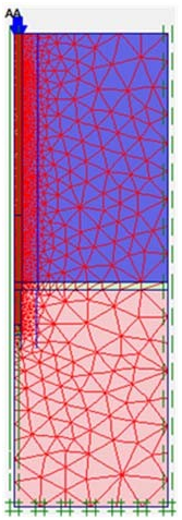
The standard fixities in PLAXIS were used to simulate the boundary conditions for the axisymmetric model. The bottom boundary is considered rigid with zero allowable displacements in both the vertical and horizontal directions while side boundaries in the form of rollers allowing for vertical deformations and preventing the lateral deformations were used.
7.4. Finite Elements Mesh
15 nodes triangular elements have been chosen. Medium coarse mesh setting with refinement of the
mesh through the pile segments were considered to generate the F.E. mesh with reasonable elements sizes. In order to minimize the side boundaries effect on the problem, several trials were carried out in which a final model with a width (radius) of 10.0 m and a rigid boundary at a depth of about 12.0 m below the socket pile tip was chosen. The boundaries at these distances were found to have almost no effect on the results. Figure (11) shows the Model with the applied vertical Stresses.
7.5. Finite Elements Analyses Results and Discussions
Three cycles of the finite elements analysis were carried out considering the three investigated constitutive models for simulating the crystalline rock salt behavior. Results of the F.E. analyses from the
load-settlement perspective are compared to the field results of the pile load test as shown in Figure (12).
Table (3) summarizes the observed and calculated pile head settlements along with the error in the settlement estimation using the different constitutive models.
a) Generally, all investigated constitutive models for simulating the crystalline rock salt behavior result in
an overestimated pile head settlement values.
b) The error in estimating the pile head settlement dramatically decreases with increasing the loading values.
c) The hardening soil model (HS) out of the three investigated constitutive models results in
estimating the head settlement of the pile socketed in the crystalline rock salt formation with the least
error. The settlement estimation error utilizing the HS model compared to the observed values from the
field test varies between approximately 30.79% at the peak of the first loading cycle to approximately
3.97% at the maximum tested load.
d) Both the LE and the MC models simulated the almost elastic behavior of the rock salt (i.e. no
residual/permanent plastic deformations after unloading). The HS model failed to simulate this phenomenon as some residual plastic deformations were observed from the F.E. analysis utilizing the
HS constitutive model for the rock salt.
For more understanding of the obtained results, the load settlement curves resulted from the F.E. analyses
using the different rock salt constitutive models are presented separately with the field curve as shown in
Figures (13 to 15). From these figures it can be noticed that the main advantage of the HS model over the other two constitutive models (LE and MC) in simulating the crystalline rock salt behavior is its ability to depict the looping phenomenon resulting mainly from using different values of the elastic deformation moduli for the loading and unloading-reloading conditions that are the E and the Eur. The LE and the MC models use the same deformation moduli for loading and unloading reloading and hence the cyclic loading ends up with identical load settlement relationship by repeating the loading process (cycling).
Furthermore, the field pile load test clearly shows an increase in the resulted vertical settlement under a
certain loading value when the load is applied (repeated) mainly for third time which means a softening in the rock associated with the cyclic loading effect. The HS model of the salt layer was considerably able to depict this phenomenon in the F.E. analysis results as shown in Figure (15), while the LE and the MC models didn’t show the same ability.
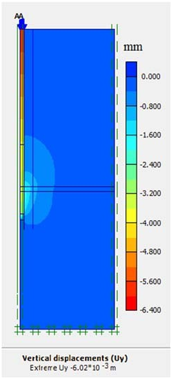
Figure (16) presents the F.E. analysis results using the HS model for the rock salt pertaining to the vertical
displacement distribution along the tested pile and within the subsurface continuum at the maximum pile load value (1680 kN). From this figure along with the analysis results, it is noticed that the average vertical deformation along the pile socket is approximately 3.0 mm while the average vertical deformation along the void at the pile tip is approximately 0.70 mm.
8. ROCK SALT DEFORMATION MODULUS FROM BACK-ANALYSIS
In order to assess the value estimated and adopted in the analyses for the rock salt deformation modulus, E, a back analysis was carried out for the monitored settlement during the pile load test under the maximum test load (5.79 mm at a load of 1680 kN) after subtracting the elastic compression of the steel pile and the concrete part socketed in the salt. The following equation derived by Pells [8] for calculating the settlement of a bored pile where the load is carried by rock socket shaft friction only was used:
Settlement = p = Q Ip / B Ed
where
Q = total load carried by the pile head
Ip = influence factor
B = diameter of the socket
Ed = deformation modulus of the rock mass surrounding the shaft.
The back-calculated value of the deformation modulus of the rock mass surrounding the pile shaft was found to be; Ed ≈ 400 MPa. This value is almost twice the maximum value calculated from the uniaxial compression tests or pressuremeter tests and also approximately twice the adopted value for the deformation modulus (E) in the F.E. analyses while it is almost 0.667 the Eur adopted value.
Comparing this resulted deformation modulus value from the back analysis with the E and Eur values used in the F.E. model justifies clearly that the HS model was more able to depict the load settlement behavior of the rock salt than the LE and the MC models especially with the prevailing cyclic loading tests. This is mainly due to using the Eur modulus value, that is more close to the back-calculated value than the E value, in the unloading reloading process which is directly associated with the cyclic loading process (i.e., for cycling loading the model will use the Eur instead of the E values).
9. SHEAR STRESSES ALONG THE PILE SOCKET
From the field pile load test results shown in Figure (6), a maximum socket friction value of about 281 kPa was reached. Figure (17) shows the shear stresses distribution along the concrete socket length from the F.E. analysis model with the HS model used for the salt layer simulation while Figure (18) shows the numerical values of the distributed shear stresses resulting from the model.

An average shear stresses value along the socket length of about 238 kPa can be calculated from the F.E. model. The difference between the average shear stresses value from the field pile load test and the F.E. results can be described in the light of Figures (17 and 18) in which a stress concentration is clearly shown at the pile tip reaching a value of about 510 kPa and hence reducing the average shear stress value along the pile socket.
10. THE ORETICAL METHODS FOR ESTIMATING THE SHEAR STRESS ALONGTHE ROCK SOCKET
Correlations between the unconfined compression strength of the rock and rock socket bond stress have been established by Horvath, Rosenberg and Williams [9, 10 and 11]. The ultimate bond stress, fs, is related to the average unconfined compression strength by the following equation [12]:
where
and are the reduction factor relating to quc and the correction factor related to the discontinuity spacing in the rock mass respectively.
| RQD (%) | Fracture Frequency per meter | Mass Factor (j) |
| 0-25 | 15 | 0.2 |
| 25-50 | 15-8 | 0.2 |
| 50-75 | 8-5 | 0.2-0.5 |
| 75-90 | 5-1 | 0.5-0.8 |
| 90-100 | 1 | 0.8-1 |
11. COMPARISON BETWEEN THE MEASURED, CALCULATED AND ESTIMATED SHEAR STRESS ALONG THE ROCK SOCKET
For the case under study of the Dead Sea rock salt with an average RQD value of about (60 to 80)% and average unconfined compressive strength of about 5.10 MPa, the ultimate bond strength can be estimated based on the method developed by Pells [8] as; (fs) ≈ 400 kPa. Applying a factor of safety of 2.0 for the normal rock socket design when ignoring the end bearing effect, results in a working bond stress of about 200 kPa. This value is close to the observed value from the field pile load test and the calculated value from the F.E. analysis.
12. CONCLUSIONS
From the presented results in this paper of the field pile load test of a single pile socketed in the crystalline rock salt layer of the Dead Sea, F.E. elements analyses performed utilizing different constitutive models for simulating the rock salt behavior, in-situ tests and back analysis of the pile load test results, the followings are
concluded:
a) The main characteristic of the rock salt of the Dead Sea is its softening after repeating of the loading
conditions. This phenomenon appears in the shape of an increase in the settlement under the same load
after being repeated (load cycling). This behavior was observed only under high-loading conditions.
b) The rock salt behavior, in the short term, can be considered as elastic where no residual (i.e. plastic
deformations) were recorded from the field pile load test results.
c) Pressuremeter tests results show that the Dead Sea rock salt gets stiffer in the unloading-reloading
condition and gets even stiffer after repeating the unloading-reloading for more than one cycle.
d) The rock mass deformation modulus (E) of the Dead Sea rock salt formation is generally higher than the values usually estimated using the RQD, mass factor (j) and the average deformation modulus of the
intact rock.
e) Using the hardening soil model (HS) for simulating the rock salt formation behavior gives a better
estimate of the pile head settlement compared to both the linear elastic (LE) and the Mohr-Coulomb
(MC) constitutive models.
f) Both the LE and the MC models simulate the almost elastic behavior of the rock salt (i.e. no residual/permanent plastic deformations after unloading). The HS model fails to simulate this
phenomenon as some residual plastic deformations were observed from the F.E. analysis utilizing the
HS constitutive model for the rock salt.
g) For modeling the cycling loading on piles using the F.E. method, the unloading-reloading deformation
modulus, Eur, is the major factor affecting the accuracy and reliability of the modeling process.
h) Theoretical methods for estimating the bond strength between rock and socketed piles as established by Horvath, Rosenberg and Williams [9,10 and 11] provide a reasonable approach for dealing with the rock salt of the Dead Sea under short-term conditions.
i) Creep effect should be considered in the long term behavior of the rock salt.


